Chapter 5 Frequency Domain Analysis of Systems
560 likes | 991 Vues
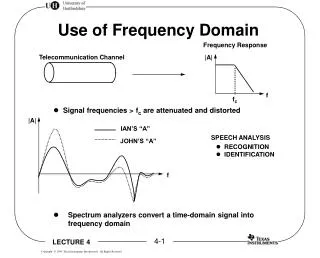
Chapter 5 Frequency Domain Analysis of Systems. CT, LTI Systems. Consider the following CT LTI system: Assumption: the impulse response h ( t ) is absolutely integrable, i.e.,. (this has to do with system stability ). Response of a CT, LTI System to a Sinusoidal Input .

Chapter 5 Frequency Domain Analysis of Systems
E N D
Presentation Transcript
CT, LTI Systems • Consider the following CT LTI system: • Assumption: the impulse response h(t) is absolutely integrable, i.e., (this has to do with system stability)
Response of a CT, LTI System to a Sinusoidal Input • What’s the response y(t) of this system to the input signal • We start by looking for the response yc(t) of the same system to
Response of a CT, LTI System to a Complex Exponential Input • The output is obtained through convolution as
The Frequency Response of a CT, LTI System is thefrequency response of the CT, LTI system = Fourier transform of h(t) • By defining it is • Therefore, the response of the LTI system to a complex exponential is another complex exponential with the same frequency
Analyzing the Output Signal yc(t) • Since is in general a complex quantity, we can write output signal’s phase output signal’s magnitude
Response of a CT, LTI System to a Sinusoidal Input • With Euler’s formulas we can express x(t) as Using the previous result, the response is
Response of a CT, LTI System to a Sinusoidal Input – Cont’d • If h(t) is real, then and • Thus we can write y(t) as
Response of a CT, LTI System to a Sinusoidal Input – Cont’d • Thus, the response to is which is also a sinusoid with the same frequency but with the amplitudescaled by the factor and with the phase shifted by amount
Example: Response of a CT, LTI System to Sinusoidal Inputs • Suppose that the frequency response of a CT, LTI system is defined by the following specs:
Example: Response of a CT, LTI System to Sinusoidal Inputs – Cont’d • If the input to the system is • Then the output is
Example: Frequency Analysis of an RC Circuit • Consider the RC circuit shown in figure
Example: Frequency Analysis of an RC Circuit – Cont’d • From EEE2032F, we know that: • The complex impedance of the capacitor is equal to • If the input voltage is , then the output signal is given by
Example: Frequency Analysis of an RC Circuit – Cont’d • Setting , it is whence we can write where and
Example: Frequency Analysis of an RC Circuit – Cont’d • The knowledge of the frequency response allows us to compute the response y(t) of the system to any sinusoidal input signal since
Example: Frequency Analysis of an RC Circuit – Cont’d • Suppose that and that • Then, the output signal is
Example: Frequency Analysis of an RC Circuit – Cont’d • Suppose now that • Then, the output signal is
Example: Frequency Analysis of an RC Circuit – Cont’d The RC circuit behaves as alowpass filter, by letting low-frequency sinusoidal signals pass with little attenuation and by significantly attenuating high-frequency sinusoidal signals
Response of a CT, LTI System to Periodic Inputs • Suppose that the input to the CT, LTI system is a periodic signalx(t) having period T • This signal can be represented through its Fourier series as where
Response of a CT, LTI System to Periodic Inputs – Cont’d • By exploiting the previous results and the linearity of the system, the output of the system is
Example: Response of an RC Circuit to a Rectangular Pulse Train • Consider the RC circuit with input
Example: Response of an RC Circuit to a Rectangular Pulse Train – Cont’d • We have found its Fourier series to be with
Example: Response of an RC Circuit to a Rectangular Pulse Train – Cont’d • Magnitude spectrum of input signal x(t)
Example: Response of an RC Circuit to a Rectangular Pulse Train – Cont’d • The frequency response of the RC circuit was found to be • Thus, the Fourier series of the output signal is given by
Example: Response of an RC Circuit to a Rectangular Pulse Train – Cont’d filter more selective
Example: Response of an RC Circuit to a Rectangular Pulse Train – Cont’d filter more selective
Example: Response of an RC Circuit to a Rectangular Pulse Train – Cont’d filter more selective
Response of a CT, LTI System to Aperiodic Inputs • Consider the following CT, LTI system • Its I/O relation is given by which, in the frequency domain, becomes
Response of a CT, LTI System to Aperiodic Inputs – Cont’d • From , the magnitude spectrum of the output signal y(t) is given by and its phase spectrum is given by
Example: Response of an RC Circuit to a Rectangular Pulse • Consider the RC circuit with input
Example: Response of an RC Circuit to a Rectangular Pulse – Cont’d • The Fourier transform of x(t) is
Example: Response of an RC Circuit to a Rectangular Pulse – Cont’d
Example: Response of an RC Circuit to a Rectangular Pulse – Cont’d
Example: Response of an RC Circuit to a Rectangular Pulse – Cont’d
Example: Response of an RC Circuit to a Rectangular Pulse – Cont’d • The response of the system in the time domain can be found by computing the convolution where
Example: Response of an RC Circuit to a Rectangular Pulse – Cont’d filter more selective
Filtering Signals • The response of a CT, LTI system with frequency response to a sinusoidal signal • Filtering: if or then or is
Four Basic Types of Filters lowpass highpass passband stopband stopband cutoff frequency bandpass bandstop
Phase Function • Filters are usually designed based on specifications on the magnitude response • The phase response has to be taken into account too in order to prevent signal distortion as the signal goes through the system • If the filter has linear phase in its passband(s), then there is no distortion
. . Ideal Sampling • Consider the ideal sampler: • It is convenient to express the sampled signal as where
Ideal Sampling – Cont’d • Thus, the sampled waveform is • is an impulse train whose weights (areas) are the sample values of the original signal x(t)
Ideal Sampling – Cont’d • Since p(t) is periodic with period T, it can be represented by its Fourier series sampling frequency (rad/sec) where
Ideal Sampling – Cont’d • Therefore and whose Fourier transform is
Signal Reconstruction • Suppose that the signal x(t) is bandlimited with bandwidth B, i.e., • Then, if the replicas of in do not overlap and can be recovered by applying an ideal lowpass filter to (interpolation filter)