DAC, Diodes, Triacs
DAC, Diodes, Triacs. ME 6405 – Intro to Mechatronics Student Lecture. Kevin Johnson Minh Vo Lam Duong Wye -Chi Chok. Kevin Johnson. Outline. DAC What is a DAC? Types of DAC Specifications Diodes What are diodes? P-N Junction Diode Real vs. Ideal Types of Diodes & Applications


DAC, Diodes, Triacs
E N D
Presentation Transcript
DAC, Diodes, Triacs ME 6405 – Intro to Mechatronics Student Lecture Kevin Johnson Minh Vo Lam Duong Wye-Chi Chok
Kevin Johnson Outline • DAC • What is a DAC? • Types of DAC • Specifications • Diodes • What are diodes? • P-N Junction Diode • Real vs. Ideal • Types of Diodes & Applications • Triacs • What are thyristors? • What are triacs? • Applications
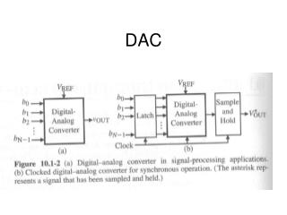
Kevin Johnson Principal components of DAC
Kevin Johnson What is a DAC? • Convert digital signal (number) to analog signal (voltage or current) • Either multiplying or non-multiplying • Non-multiplying contains its own reference • Multiplying takes external reference. • Two main types: ladder and delta-sigma
Analog Output Signal Digital Input Signal Kevin Johnson DAC ideal output. • Each binary number sampled by the DAC corresponds to a different output level.
Ideally Sampled Signal Output typical of a real, practical DAC due to sample & hold Kevin Johnson DAC real output. DACs capture a number and hold that value for a given sample interval. This is known as a zero-order hold and results in a piecewise constant output. DAC
Smoothing Kevin Johnson Piece-wise Continuous Output Analog Continuous Output Digital Input n bit DAC 0 bit 011010010101010100101 101010101011111100101 000010101010111110011 010101010101010101010 111010101011110011000 100101010101010001111 Filter nth bit Used when a continuous analog signal is required. Signal from DAC can be smoothed by a Low pass filter
Kevin Johnson Applications. • Motor, valve, actuator • Rarely; usually PWM. • Audio/Video • MP3 players • Cellphones • Television • (well, old ones) • Signal Generators • Sine wave generation • Square wave generation • Triangle wave generation • Random noise generation
Kevin Johnson Types of DAC implementations • Binary Weighted Resistor • R-2R Ladder • Pulse Width Modulator (not covered) • Oversampling DAC, aka Delta Sigma (used internally in HCS12)
Binary Weighted Resistor Assume binary inputs B0 (LSB) to Bn-1 (MSB) Each Bi is 1 or 0 and is multiplied by Vref to get input voltage Kevin Johnson B5 B4 B3 B2 B1 B0
Kevin Johnson Binary weight theory • Need to fill jars to a specific level using set of measuring cups. • Cups are ½, ¼, 1/8, 1/16, etc. http://www.msbtech.com/support/How_DACs_Work.php
Kevin Johnson BWR Pros and Cons • Advantages • Simple • Fast • Disadvantages • Need large range of resistor values (2048:1 for 12-bit) with high precision in low resistor values • Need very small switch resistances • Op-amp may have trouble producing low currents at the low range of a high precision DAC
Kevin Johnson R-2R ladder basic circuit • Equivalent resistance to ground at each top node is R. • At each node, current gets split in two. • Since nodes are cascaded, currents are ½, ¼, 1/8, etc.
Kevin Johnson R-2R Ladder results • Final result is: • Assuming Rf = R (and ignoring negative) • Resolution is smallest step: i.e. B=1 in above equation.
R-2R Ladder Advantages: Only 2 resistor values Lower precision resistors acceptable Disadvantages Slightly slower conversion rate Op-amp must still handle very small currents at high bit numbers. Kevin Johnson
Kevin Johnson Delta-sigma DAC • Now all cups are the same size (or more precisely, he uses the same cup over and over). • Cup size is 1/(2^n). • He must add this amount the proper number of times (pulse-count modulation). http://www.msbtech.com/support/How_DACs_Work.php
Kevin Johnson Delta-sigma Pros and Cons • Pros: • Very accurate • High bit-depth possible • Reduced aliasing • Cons: • Requires very fast oversampling clock. • At least 2^n times faster than sampling rate • Complicated • Sensitive to clock jitter
General comments Circuits as shown produce only unipolar output Replacing ground with –Vref will allow Vout to be positive or negative Kevin Johnson
Specifications of a DAC Reference Voltage Resolution Sampling Rate Settling Time Linearity Errors Minh Vo
Reference Voltage Vref Determines the output voltage range Non-multiplying DAC Fixed Vref set internally by manufacturer Multiplying DAC Vref is set externally and can be vary during operation Full-scale voltage Vfs Voltage when all digital inputs are 1’s Minh Vo
Resolution The resolution is the amount of output voltage change in response to a least significant bit (LSB) transition. Smaller resolution results in a smoother output A common DAC has a 8 - 16 bit resolution Minh Vo
Sampling Rate fsampling Rate of conversion of a single digital input to its analog equivalent When the input changes rapidly, fmax, the DAC conversion speed must be high Nyquist Criterion: Limited by the clock speed of the input signal and the settling time of the DAC Minh Vo
Settling Time DAC needs time to reach the actual expected analog output voltage The time required for the output voltage to settle within +/- ½ of VLSB of the expected voltage Minh Vo
Linearity The difference between the desired analog output and the actual output over the full range of expected values Minh Vo Linear (Ideal) Non-Linear
Errors Gain Error Offset Error Full Scale Error Non Linearity Non-Monotonic Resolution Errors Settling Time and Overshoot Minh Vo
Gain Error Deviation in the slope of the ideal curve and with respect to the actual DAC output High Gain Desired/Ideal Output Analog Output Voltage Low Gain Digital Input Minh Vo High Gain Error: Step amplitude is higher than the desired output Low Gain Error: Step amplitude is lower than the desired output Gain Error is adjustable to zero using an external potentiometer
Offset Error Occurs when there is an offset in the output voltage in reference to the ideal output Minh Vo This error may be detected when all input bits are low (i.e. 0). Output Voltage Desired/Ideal Output Positive Offset Digital Input NegativeOffset
Full Scale Error Combination of gain and offset error Minh Vo
Differential Non-Linearity Voltage step size changes vary with as digital input increases. Ideally each step should be equivalent. Ideal Output Analog Output Voltage Diff. Non-Linearity = 2VLSB 2VLSB VLSB Digital Input Minh Vo
Integral Non-Linearity Occurs when the output voltage is non linear. Basically an inability to adhere to the ideal slope. Minh Vo Ideal Output Analog Output Voltage Int. Non-Linearity = 1VLSB 1VLSB Digital Input
Non-Monotonic Occurs when the an increase in digital input results in a lower output voltage. Minh Vo Desired Output Non-Monotonic Monotonic Analog Output Voltage Digital Input
Resolution Errors Does not accurately approximate the desired output due large voltage divisions. Poor Resolution(1 bit) Vout Desired Analog signal 1 2 Volt. Levels 0 0 Digital Input Approximate output Minh Vo
Settling Time and Overshoot Any change in the input time will not be reflected immediately due to the lag time. Overshoot occurs when the output voltage overshoots the desired analog output voltage. Minh Vo
Lam Duong What is a Diode? • A diode is a two terminal electric component which conducts current more easily in one direction than in the opposite direction. • The most common usage of a diode is as an electronic valve which allows current to flow in one direction but not the opposite direction.
Lam Duong A bit of history • Diodes were known as rectifiers until 1919, when a physicist by the name of William Eccles coined the term diode, which from its Greek roots means “through-path.” • In 1873 Fredrick Guthrie discovered thermionic diodes (vacuum tube diodes) . Heating the cathode in forward bias permitted electrons to be transmitted into the vacuum, but in reverse bias the electrons were not easily release from the unheated anode.
Lam Duong A bit of history • In 1874 Karl Braun discovered the first solid state diode (crystal diode). It consists of using Galena crystals as the semiconducting material. • In 1939 Russell Ohl discovered the first P-N junction at Bell Labs. • Today, the majority of diodes are made of semiconductor silicon P-N junctions.
Majority carriers p n Depletion Region Lam Duong P-N Junction Diode • A P-N junction diode consists of a p-type semiconductor (silicon) joined with an n-type semiconductor. • P-type – A semiconductor doped with impurities to create positive charge carriers (holes). • N-type – A semiconductor doped with impurities to create negative charged carriers. • A depletion region is created when negative charge carriers from the N-type region diffuse into the P-type region, and vice versa.
P-N Junction Diode The behavior of a diode depends upon the polarity of the supply voltage. Under forward bias the depletion region is reduced in size and less energy is required for the charged majority carriers to cross the depletion region. This decrease in energy requirement results in more charged majority carriers to cross the depletion region which induces a current. Depletion Region p n if Forward Biased Lam Duong
P-N Junction Diode Under reverse bias the depletion region is greatly increased in size and requires significantly more energy from the majority carriers in order to cross. Most majority carriers won’t be able to cross the depletion region and thus are unable to induce a current. p n Reverse Biased Lam Duong Depletion Region ir V
I conduction region V non-conduction region Ideal Curve Lam Duong Real vs. Ideal • Ideal P-N Diode – no resistance to current in forward bias and infinite resistance in reverse bias. (Similar to a switch) • In reality there is resistance to current flow in forward bias. It requires a certain voltage to be reached before the depletion region is eliminated and full current flow is permitted. • Likewise, in reverse bias there is a small reverse (leakage) current induced by the flow of minority carriers. At a certain voltage (break down voltage) the reverse current will increase significantly. This is called the Avalanche current.
Lam Duong Schottky Diode • Unlike P-N junction diodes, Schottky diodes are based on a metal and semiconductor junction. • An advantage of Schottky diodes over P-N junction diodes is that Schottky diodes have no recovery time when switching from conducting to non-conducting state and vice versa. • The main disadvantage of Schottky diodes are that they operate in low voltage compare to P-N junction diodes (up to 50V). • Another significant difference is that the “on-voltage” for a Schottky diode is around .3V while it is .7V for a P-N junction diode. Metal N-Type
Lam Duong Flyback Diode • Schottky diodes are often used as Flyback diodes due to their quick recovery and low forward voltage drop. • A Flyback diode is a diode used to eliminate the sudden voltage spike that occurs across an indicutive load when voltage is abruptly reduced or removed. • Lenz’s law - if the current through an inductance changes, this inductance induces a voltage so the current will go on flowing as long as there is energy in the magnetic field. • Flyback diodes are important in mechatronics applications where one may want to vary the voltage of an inductive load to control its operation.
Lam Duong Other Types of Diodes • Light Emitting Diodes (LEDs) - A diode formed from a semiconductor such as gallium arsenide, carriers that cross the junction emit photons when they recombine with the majority carrier on the other side. • Photodiode – Exploits the fact that all semiconductors are subject to charged carrier generation when they are exposed to light. Photodiodes are often used to sense light such as in an Opto-isolator. • Zener Diode – Allows current in forward bias like a regular diode, but also in reverse bias if the voltage is larger than designed voltage, called the Breakdown voltage.
Wye-Chi Chok What are TRIACS? In order to know, we must first look at thyristors…
Wye-Chi Chok What are Thyristors? • Class of semiconductor components that can only go in 1 direction. • Wide range of devices, SCR (silicon controlled rectifier), SCS (silicon controlled switch), Diacs, Triacs, and Shockley diodes • Used in high power switching applications i.e. hundreds of amps / thousands of watts
Wye-Chi Chok How do Thyristors work? • PNPN (4-layer) device: • PNP and NPN transistor back-to-back. • With forward voltage, small gate current pulse turns on device. • once on, each transistor supplies gate current for the other, so no need for gate input • only way to turn it off is to stop current (i.e. bring voltage to zero)
Wye-Chi Chok Thyristors cont’d.
Wye-Chi Chok …now then, what are TRIACS? • A TRIAC (TRIode for Alternating Current) is a 3-terminal AC semiconductor switch. • Composed of 2 thyristors facing opposite directions such that it can conduct current in either direction. • MT1 and MT2 are current carrying terminals while the Gate terminal is used for triggering by applying a small voltage signal. • Once triggered, it continues to conduct current until the current falls below a threshold value.
Wye-Chi Chok Triac Operation • 5 layer device • Region between MT1 and MT2 are parallel switches (PNPN and NPNP) • Allows for positive or negative gate triggering
Wye-Chi Chok Triac Characteristic Curve