Pump World pumpworld/contents.htm
180 likes | 403 Vues
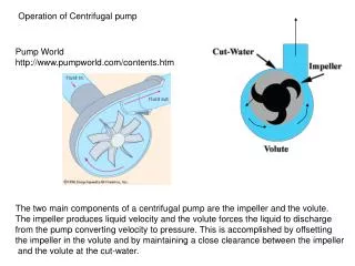
Operation of Centrifugal pump. Pump World http://www.pumpworld.com/contents.htm. The two main components of a centrifugal pump are the impeller and the volute. The impeller produces liquid velocity and the volute forces the liquid to discharge

Pump World pumpworld/contents.htm
E N D
Presentation Transcript
Operation of Centrifugal pump Pump Worldhttp://www.pumpworld.com/contents.htm The two main components of a centrifugal pump are the impeller and the volute. The impeller produces liquid velocity and the volute forces the liquid to discharge from the pump converting velocity to pressure. This is accomplished by offsetting the impeller in the volute and by maintaining a close clearance between the impeller and the volute at the cut-water. Pump Worldhttp://www.pumpworld.com/contents.htm Pump Worldhttp://www.pumpworld.com/contents.htm
Typically constant speed electrical motors operate pumps. This means that for a given pump there is a discrete set of operating speeds
h, P h Q For a GIVEN pump operating at a given speed we can plot a Performance Curve The shutoff head the maximum head that can be provided—the pump can lift water to this height BUT water can not flow (Q = 0) The free-delivery This is the maximum flow through the pump. It can only be achieved if no pipe is attached to the pump ( hP = 0). Pump Efficiency
h, P h And define the Best Efficiency Point BEP Q For a GIVEN pump operating at a given speed we can plot a Performance Curve Power See Fig 14.9 in Book We attempt to size our pump so that the head required is as close as possible To the BEP
h h Q Operating Point In addition to the head provided by the pump we also have the the system curve which says how the head required changes with Q Operating point: the head that a given speed pump will operate at We attempt to size our pump so that the operating point is as close as possible To the BEP
The performance of Similar Pumps can be represented by A single Dimensionless Performance Curve see 14.10 which can be used to size the pump for the job
Dimensionless Pump Performance –see Fig 14.10 6 CH 1 Head Coef. Power Coef. Capacity Coef. CP and efficiency h CH CP 0 0 CQ DH head required, Diameter of impeller, P power n revolutions per second, Note n rotational speed. Some times this is written as N –revs per MINUTE If you are given an angular speed (w radians per second)
14.21 A pump defined by Fig 14.9 –pumps water from, 366 to 450 m through A 0.36 m steel pipe 610 m long. What is Q for Pipe Solve by Iteration Head required is = 450-366 + head loss (hL) in Pipe—Guess 90 (hL = 6) 14.9 Q = 0.24 m3/s Relative Roughness ks/D = 0.00012 V=Q/A=2.36 m/s Find f from Moody hL = 6.7 14.9 Q = 0.23 m3/s
!4.22 If the pump in Fig 14.9 and Fig 14.10 is operated at 1500 rpm what is Discharge when the head is 150 ft From Fig 14.9 we know D = 37. 1cm = 1.217 ft Fig 14.10 CQ = 0.122 Q = 5.5 ft3/s
14.25 Fig 14.10 pump has a D = 0.4 m and operates at 25 rps What is discharge when head is 50 m 14.10 CQ=0.13 Q = 0.208 m3/s
Specific speed NOT dimensionless ns In selecting a pump a rule of thumb An axial Flow pump is suited for low heads and high discharge Radial flow for higher heads and lower discharge We can be a little more precise in pump style selection by defining the specific speed obtained by combing CH and CQ to eliminate the size factor D Radial Mixed Axial This value can be used to select the correct style of pump (radial, mixed or axial) (see Fig 14.14)
Suction Limit and Cavitation The Net Positive Suction HeadNPSH is defined as the pump head on the suction side of the pump minus the vapor pressure (expressed as head). (see example 14.7 on page 596) Note: Typically ps ~ atmospheric pressure. Pressure is ABSOLUTE In US dimensioned system we can also define a suction specific speed (SI dimensionless form given on page 597) A value of S < 8500 is usually safe from cavitaion Note in Roberson and Crowe S = Nss ; 1 cfs = 449 gpm = 0.02832 m3/s 1 m3/s = 15,854 gpm
14.29 What is the suction specific speed for the pump of Figure 14.7—page 586 When the discharge is Q = 0.22 m3/s and velocity 2.21 m/s (answer of problem 4.13). Is it safe. n = 11.5 rps, N = 690 rpm Q = .22 m3/s = 3488 gpm D=.356 From Figure 4.13 (axial flow pump) < 8500 so OK
14.32 What type of pump should be used to pump at Q =0.4 m3/s Under a head of 70 m if N = 1100 rpm Use Fig 14.14 and definition of specific speed Fig 14.14 Radial Flow
6 CH h CH 0 0 CQ Steps in Pump sizing –see Lab For a given pump motor frequency and type and Design discharge we can Identify a pump speed N that will not cause cavitation Could meet Design by using Pumps in series or parallel see Fig 14.9 (601) With Known N use dimensionless Pump performance curve (supplied by manufacturer) From definitions Can calculate diameter of pump and head delivered May require some iteration and use of pumps in parallel to meet Design Head required