Understanding Digital Circuits: The Fundamentals of Electrical Engineering
Digital circuits are essential building blocks in electrical engineering, utilized in computers, control systems, LED displays, and more. This guide explains the fundamentals of digital logic, binary representation, and logic gates, including AND, OR, NOT, and NAND gates. Learn how voltage signals represent binary information and explore truth tables and operations on logic circuits. With practical examples like flip-flops and hands-on circuit-building activities using breadboards, this resource provides a comprehensive introduction to digital circuits and their applications in modern technology.


Understanding Digital Circuits: The Fundamentals of Electrical Engineering
E N D
Presentation Transcript
Digital Circuits A key element of electrical engineering sources:http://www.facstaff.bucknell.edu/mastascu/eLessonsHTML/EEIndex.html http://www.jhu.edu/~virtlab/logic/log_cir.htm
Foundations of Electrical Engineering • Electrophysics • Maxwell's Equations, Circuit theory • Information (Communications) Theory • Data rate vs Signal Strength, Error correction • Digital Logic • Using Logic Gates to build up complex ccts 2
EE Subdisciplines • Power Systems • Electromagnetics • Solid State • Communication/Signal Processing • Controls • Analog/Digital Design 3
H2O Low Pressure High Pressure What is Voltage? V = “Electrical pressure” - measured involts. Figure 1.1
A battery in an electrical circuit plays the same role as a pump in a water system.
Where can I find a digital circuit? • Digital Circuits and Digital Logic are the buiding blocks for • computers • certain control systems (robots, factories) • LED displays • Digital Circuits are built up from Analog circuits • analog: continuous varying, digital: discrete steps • electricity has many characteristics of logic (+/-, True/False, etc)
Digital Logic is based on Binary • Two possible states • True/False • 1/0 • Yes/No • On/Off • Light/Dark
Logic Signals • Different systems for representing binary info in the physical world: • A voltage signal: • Zero (0) corresponding to 0 volts • One (1) corresponding to five volts. • A sinewave: • Zero corresponding to some frequency • One corresponding to some other frequency. • Switches: • OPEN for "0" and CLOSED for "1". • (And there are more ways!)
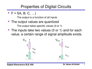
Characteristics of Logic Signals • Change in time • Initially we look at unchanging values • Voltage signal takes on two values • corresponding to 0 and 1. • for example, 0 Volts and 5 volts • We can associate a variable with a logic signal • assign a symbol to represent that variable • like the symbol A.
Think Binary! • Examples: • Cell phone converts voice into series of ones and zeros • Thermostat: 1 when temp is too low, 0 when too high • Logic signal, A, takes on values of 0 (FALSE, OFF) or 1 (TRUE, ON). • might be a voltage, a switch closure, etc. • More generally, think in terms of zeros and ones • not in terms of the values of the voltage or switches.
Operations on Logic Circuits • Suppose there are 2 logic signals. A and B • We often want to derive a 3rd signal C based on the values of A and B • if it is dark outside (A) OR raining (B) • Turn on lights (C) OR GATE
Logic Gates • Logic Gates are digital circuit packages that perform logic operations on logic signals • AND gate: both must be true for true output • OR gate: only one must be true for true output • NOT gate: true in means false out and vice versa • NAND gate: the opposite of AND • AND followed by NOT
Truth Tables and Logic Gates • Truth tables use 1/0 instead of True/False • OR AND NOT (inverter)
NAND GATE = NOT AND A B C • An AND gate • followed by NOT • Truth Table Usually drawn as: A B C Any logic gate can be builtfrom 1 or more NAND gates!
Lab: LS7400 Quad Nand Gate IC • Pinout shows which pins are connected to what • Vcc = +5 V, -Vcc = 0V • Verify the notch location!!
Breadboard a NAND gate • a breadboard is a quick way to build circuits without soldering • 5 pin rows are connected by metal clips • vertical column on sides are connected.
Connect Power Supply to Breadboard Ground+5V Black to GroundRed to +5V
Add LEDs to show value of A,B(1- 470 Ohm Resistor for each LED) The shorter Wire on LED goes to GROUND When both are connected, turn on power (A, B are '1')
Move brown wire to change B to '0' Add LED to output pin 3
A NAND Inverter • Connecting the two inputs • A and B are both at A • Truth table is the same as Inverter A C
NAND + NAND = AND • Taking NOT-NOT AND A B C Try it! Add wires from Pin 3 to 4, 4 to 5 move your output Resistor to pin 6
FLIP FLOP – another 2 NAND cct • Output of 1 (P) • feeds back to input of 2 • Output of 2 (Q) • feeds back to input of 1 MEMORY!! previous state was X=1, Y=0 previous state was X=0, Y=1
Flip Flop Wiring And each labelled pin A,B,P,Q have resistors and LED to ground for monitoring
Flip Flop in Action A=0 B=1 A=0 B=0
Flip Flop in Action A=0 B=1 A=1, B=1 A=1 B=0 A=1, B=1
3 NANDs make an OR A C B Use the digital circuit simulator to try out:http://www.jhu.edu/~virtlab/logic/logic.htm
Team Challenges (simulate or wire up) Using only NAND gates: A . Design, construct and test a three input AND. B. Design, construct and test a three input NAND. C. Design a four input NAND. Hint: If wiring, use an LED indicator to show the inputs and/or the outputs in your circuits. Use a current-limiting resistor for each LED.
Use the circuit builderhttp://www.jhu.edu/~virtlab/logic/logic.htm D. Using only AND, NOT, and OR produce a three-input OR circuit, ie., the output is 1 if any of the inputs is 1. E. Create a two-input "adder" with two outputs: the one-digit result of the add, and the value of a "carry" bit. In binary arithmetic, 1+1=0 with a carry=1.
Super Bowl Problem • At the beginning of halftime during the Superbowl, • 35 million toilets are flushed almost simultaneously. • Resulting loss of water pressure wreaks havoc on many municipal water systems. • Make a controller to solve the problem for a "three toilet" system. • Devise a logic circuit whose "1" inputs represent "flushes" • and whose "1" outputs represent opened water valves • If no more than one toilet is flushed, then that toilet's water valve opens, • the others remaining closed. • If more than one toilet is flushed, then all the water valves remain closed.