Chap. 9 Sinusoidal Steady-State Analysis
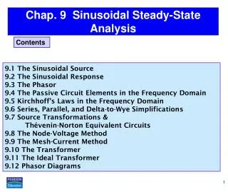
Chap. 9 Sinusoidal Steady-State Analysis. C ontents. 9.1 The Sinusoidal Source 9.2 The Sinusoidal Response 9.3 The Phasor 9.4 The Passive Circuit Elements in the Frequency Domain 9.5 Kirchhoff’s Laws in the Frequency Domain 9.6 Series, Parallel, and Delta-to-Wye Simplifications

Chap. 9 Sinusoidal Steady-State Analysis
E N D
Presentation Transcript
Chap.9Sinusoidal Steady-State Analysis Contents 9.1 The Sinusoidal Source 9.2 The Sinusoidal Response 9.3 The Phasor 9.4 The Passive Circuit Elements in the Frequency Domain 9.5 Kirchhoff’s Laws in the Frequency Domain 9.6 Series, Parallel, and Delta-to-Wye Simplifications 9.7 Source Transformations & Thévenin-Norton Equivalent Circuits 9.8 The Node-Voltage Method 9.9 The Mesh-Current Method 9.10 The Transformer 9.11 The Ideal Transformer 9.12 Phasor Diagrams
9.1 The Sinusoidal Source > 0 sinusoidal source peak oramplitude angular frequency: <radians/second> period frequency) <cycles/second> (Hz) phase angle: 2 2
Root Mean Square, rms, Value:the square root of the mean value of the squared periodicfunction Rms, or effective value, 3
EX 9.1 Finding the Characteristics of a Sinusoidal Current A sinusoidal current has a maximum amplitude of 20 A. The current passes through one complete cycle in 1 ms. The magnitude of the current at zero time is 10 A. a) What is the frequency of the current in hertz (Hz)? b) What is the angular frequency in radians per second? c) Write the expression for i(t)using the cosine function. Express in degrees. d) What is the rms value of the current? a) b) c) & d) rms value = 4
EX 9.2 Finding the Characteristics of a Sinusoidal Voltage & f = 2.778= A sinusoidal voltage is given by the expression a) What is the period of the voltage in milliseconds? b) What is the frequency in hertz? c) What is the magnitude of v at t = 2.778 ms? d) What is the rms value of v ? a) b) & c) d) 5
EX 9.3 Translating a Sine Expression to a Cosine Expression Translate the sine function to the cosine function by subtracting 90◦ (π/2 rad) from the argument of the sine function. a) Verify the above translation. b) Express sin(ωt + 30◦) as a cosine function. a) Let & b) 6
9.2 The Sinusoidal Response 當開關閉合後,即 KVL 穩態解之特性 1. 穩態解仍為弦波函數。 2. 對線性電路而言,響應信號之頻率與電源信號之頻率相同。 (非線性電路除外) 3. 一般而言,穩態響應之最大振幅與電源之最大振幅不同。 4. 一般而言,響應信號之相位角不同於電源之相位角。 弦波電源 其解為: 穩態成分 steady-state component 呈弦波變化之形式持續存在 暫態成分 transient component 隨時間的增加而呈指數形式降低直至消失 8 8
9.3 The Phasor 虛部(imaginary part) 實部(real part) 相量(phasor): 是一個包含振幅(大小)及相位角的複數,但隱藏頻率。 Euler’s identity 含有一已知弦波函數之振幅及相位角,將此複數定義為弦波函數之相量表示法(phasor representation)或相量轉換(phasor transform) : 用粗黑體字代表相量,而相量轉換將弦波函數由時域轉換至複數領域, 或稱為頻域(frequency domain)。 相量轉換 & 9
Inverse Phasor Transform P-1 注意: • 暫態成份隨時間持續而消失,穩態成份必能滿足原微分方程式。 • 在弦波電源驅動的線性電路,其穩態響應仍為弦波形式,且具有相同的頻率。 • 穩態解的形式為R{Aejejt},其中A是響應之最大振幅,而是其相位角。 • 當以前述穩態解的形式代入原微分方程式,其指數項次ejt將可消去,僅留下複數頻域下求解A和的運算式。 相量轉換可將穩態弦波響應之最大振幅與相位角問題,轉換為複數的代數運算。 10
Example (利用相量求穩態響應) Note: If then 令其穩態解為 代入 若改以sin為電源,則 重要提醒: 相量讓你輕鬆做頻域與時域的轉換;電路分析時,其解請以頻域或時域表示,切勿同時包含頻域與時域。 11
EX 9.5 Adding Cosines Using Phasors If and express y = y1 + y2 as a single sinusoidal function. a) Solve by using trigonometric identities. b) Solve by using the phasor concept. a) b) 12
9.4 The Passive Circuit Elementsin the Frequency Domain The V-I Relationship for a Resistor 時域 頻域 由於電阻本身為一純量,故跨於電阻兩端之電壓相量應與通過電阻之電流相量同相(in phase)。 13 13
The V-I Relationship for an Inductor 時域 頻域 電感器的電壓相量領先電流相量90°,或是電流相量落後電壓相量90°。 14 14
The V-I Relationship for a Capacitor 時域 頻域 電容器的電壓相量落後電流相量90°,或是電流相量領先電壓相量90°。 15
Impedance and Reactance Definition of Impedance: 阻抗的定義 • 電阻器的阻抗(impedance) 為R, 電感器的阻抗為jL, 電容器的阻抗為1/jC。 • 阻抗的單位為歐姆,要注意是,雖然阻抗可能是複數,但它卻不是相量。 • 阻抗的虛部稱為電抗(reactance) 。 16
9.5 The Kirchhoff’s Laws in the Frequency Domain = 0 頻域 頻域 KVL in the Frequency Domain 時域 KCL in the Frequency Domain 時域 17 17
9.6 The Series, Parallel, and Delta-to-Wye Simplifications Combining Impedances in Series and Parallel 等效阻抗等於各阻抗之總和 等效阻抗之倒數等於各阻抗倒數總和 見下一頁之定義 18 18
Addmitance and Susceptance Definition of Admittance: 導納的定義 導納 電導(conductance) 電納(susceptance) • 電阻器的導納(addimitance) 為電導G, 電感器的導納為1/jL, 電容器的導納為jC。 • 導納的單位為西門子(siemens),導納可能是複數,但不是相量。 • 導納的虛部稱為電納(susceptance) 。 19
EX 9.6 Combining Impedances in Series 750 cos(5000t + 30◦)V a) Construct the frequency-domain equivalentcircuit. b) Calculate the steady-state current iby the phasormethod. a) b) 20
EX 9.7 Combining Impedances in Series and in Parallel 8cos200,000tA • Construct the frequency-domain equivalentcircuit. • b) Calculate the steady-state v, i1, i2, andi3by the phasormethod. a) b) 21
Delta-to-Wye Transformations Y Y 阻抗之Δ-Y 轉換公式與電阻之Δ-Y 轉換關係相似。 請參考3.7節及問題3.61。 22
EX 9.8 Using a Delta-to-Wye Transform in the Frequency Domain 23
9.7 The Source Transformations and Thévenin-Norton Equivalent Circuits 在頻域的戴維寧─諾頓等效電路之計算方法與電源轉換之觀念與純電阻電路相同,除了將等效電阻用一阻抗替代。 25
EX 9.10 Finding a Thévenin Equivalent KVL Also, 27
9.8 The Node-Voltage Method 節點1: 節點2: 控制變數: 節點1: 節點2: EX 9.11 Using the Node-Voltage Method in the Freq. Domain 29
9.9 The Mesh-CurrentMethod 網目1: 網目2: EX 9.12 Using the Mesh-Current Method in the Freq. Domain 網目1: 網目2: 控制變數: 30
9.10 The Transformer Let The Analysis of a Linear Transformer Circuit • 一次繞組(primary winding) • 連接至電源端 • 二次繞組(secondary winding) • 連接至負載端 一次繞組自感值(L1) 二次繞組自感值(L2) 互感值(M) 一次繞組電阻值(R1) 二次繞組電阻值(R2) 31 阻抗Zab與變壓器之磁極性無關
Reflected Impedance 反射阻抗(reflected impedance, Zr) : 變壓器二次側繞組及負載阻抗反射到一次側之等效阻抗 線性變壓器將二次側自阻抗的共軛值反射至一次側,且乘上一常數倍。 32
EX 9.13 Analyzing a Linear Transformer (Frequency Domain) The parameters of a certain linear transformer are R1 = 200, R2= 100, L1 = 9 H, L2 = 4 H, and k = 0.5. The transformer couples an impedance consisting of an 800 resistor in series with a 1 µF capacitor to a sinusoidal voltage source. The 300 V (rms) source has an internal impedance of 500 + j 100 and a frequency of 400 rad/s. 33
EX 9.13 Analyzing a Linear Transformer (Contd.) c d Thevenin’s Equiv. Open circuit: 34
9.11 The Ideal Transformer • 理想變壓器(ideal transformer) 的特性: • 耦合係數k = 1。 • 每一線圈的自感值為無限大(L1 = L2 = ∞)。 • 因寄生電阻產生之線圈損失可忽略不計。 Exploring Limiting Values 35
Exploring Limiting Values (Contd.) Terminal Behavior of the ideal transformer 同理 • 理想變壓器: • 各線圈之每匝伏特數之 • 絕對值相等,即 • 2. 各線圈之安培-匝數之 • 絕對值相等,即 Reflected Impedance 36
Determining the Voltage and Current Ratios & 理想變壓器的電壓關係 理想變壓器的電流關係 37
Determining the Polarity of the Voltage and Current Ratios 理想變壓器的黑點規則(Dot Convention) • 當線圈電壓V1及V2在黑點端同為正或負時, • 採正號,否則採負號。 • 2. 當線圈電流I1及I2同為流入或流出黑點端時, • 採負號,否則採正號。 38
Three ways to show the Turns Ratio 匝數比(Turns Ratio): For a = 5 39
EX 9.14 Analyzing anIdeal Transformer Ckt. (Frequency Domain) If vg =2500 cos 400tV, find the steady-state expressions for (a) i1 ; (b) v1 ; (c) i2 ; and (d) v2 . & a) Also, 40
EX 9.14 (Contd.) b) c) d) 41
The Use of an Ideal Transformer for Impedance Matching 將理想變壓器二次側負載阻抗反射至一次側時,須乘上1/a2。 42
9.12 Phasor Diagrams The complex number −7 − j 3. A graphic representation of phasors. A phasor diagram shows the magnitude and phase angle of each phasor quantity in the complex-number plane. Phase angles are measured counterclockwise from the positive real axis, and magnitudes are measured from the origin of the axes. Twodifferentmagnitude scales are necessary, one for currents and one for voltages. 43
EX 9.15 Using Phasor Diagrams to Analyze a Circuit Find the value of Rthat will cause the current through that resistor, iR, to lag the source current, is, by 45◦ when = 5 krad/s. By KCL 44
EX 9.16 Analyzing Capacitive Loading Effects Use phasor diagrams to explore the effect of adding a capacitor across the terminals of the load on the amplitude of Vsif we adjust Vsso that the amplitude of VLremains constant. Utility companies use this technique to control the voltage drop on their lines. 45