PET Fundamentals: Electronics (1)
800 likes | 1.03k Vues
PET Fundamentals: Electronics (1). Wu, Jinyuan Fermilab Apr. 2011. Fermi National Accelerator Laboratory. Colliding Experiments. Questions. PET? 511 keV ? Back to Back? Speed of Light? ADC? TDC? FPGA?. PET Electronics Overview. Things to Measure. Array of Scintillator Crystals.

PET Fundamentals: Electronics (1)
E N D
Presentation Transcript
PET Fundamentals: Electronics (1) Wu, Jinyuan Fermilab Apr. 2011
Fermi National Accelerator Laboratory PET Fundamentals: Electronics (1)
Colliding Experiments PET Fundamentals: Electronics (1)
Questions • PET? • 511 keV? • Back to Back? • Speed of Light? • ADC? • TDC? • FPGA? PET Fundamentals: Electronics (1)
PET Electronics Overview PET Fundamentals: Electronics (1)
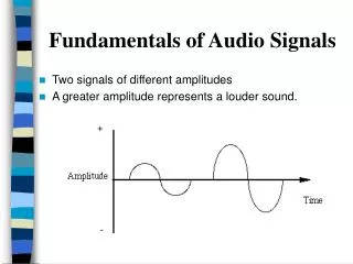
Things to Measure Array of Scintillator Crystals Photomultiplier Tubes (From Talk by Bill Moses, Search “OpenPET”) • Total Charge: • Charge is measured to calculate the photon energy. • Hit Time: • To pair up two hits, timing resolution about 1 ns is needed. • To improve imaging quality, time-of-flight (TOF) measurement good to ~50 ps is needed. • Hit Position: • The positions crystals being hit are end points of the chord line. PET Fundamentals: Electronics (1)
“Singles Event” “Singles Event” • Position (crystal of interaction) • Time Stamp (arrival time) • Energy Validation (=511 keV?) • Position (crystal of interaction) • Time Stamp (arrival time) • Energy Validation (=511 keV?) t What Is The Electronics Concept? (From Talk by Bill Moses, Search “OpenPET”) • Identify “Singles Events” • Find Time Coincidences Between Singles Events w/ t • “Coincident Event” = Pair of Singles Events PET Fundamentals: Electronics (1)
Energy Validation Shaper LP Filter ADC S PMT PET Fundamentals: Electronics (1)
Coincidence? Single Single Single Single Coincidence Coincidence Coincidence Coincidence Coincidence Single Single Single Single Single Single Single Single Single Single Single Single Single Single Single Single Single Single tmax Identifying Time Coincidences Slice 1 Slice 2 Slice 3 Slice 4 Slice 5 Slice 6 Time (From Talk by Bill Moses, Search “OpenPET”) • Break Time Into Slices (100–250 ns / slice) • Search for Singles Within tmax (4–12 ns) in Each Slice PET Fundamentals: Electronics (1)
PET Detector Module (From Talk by Bill Moses, Search “OpenPET”) Profile through Row 2 Array of Scintillator Crystals Y-Ratio Photomultiplier Tubes X-Ratio Decode Crystals Using Anger Logic (Light Sharing) PET Fundamentals: Electronics (1)
1 2 3 4 5 6 7 1 2 3 4 5 6 7 8 9 10 11 12 13 14 8 9 10 11 12 13 14 A B 15 16 17 18 19 20 21 15 16 17 18 19 20 21 22 23 24 25 26 27 28 29 30 31 32 33 34 35 22 23 24 25 26 27 28 36 37 38 30 40 41 41 C D 43 44 45 46 47 48 49 29 30 31 32 33 34 35 50 51 52 53 54 55 56 42 38 39 36 37 40 41 E=A+B+C+D Y=(A+B)/E X=(B+D)/E 43 44 45 46 47 48 49 50 51 52 53 54 55 56 Position Identification (From Talk by Bill Moses, Search “OpenPET”) Y X • Identify Crystal of Interaction Using Lookup Table • Position Given by Crystal ID PET Fundamentals: Electronics (1)
Vin Vin Vin Vin ADC ADC ADC ADC Vref Vref Vref Vref OpenPET Implementation (~2010) Free-Running (~75 MHz) PMTs Gain Adjust, Anti-Alias FPGA & Memory A A Crystal Lookup (X & Y ID) EnergyValidation (E & ID 511?) Time Stamp (T & ID T Stamp) Event Formatting +5V Gain Adjust, Anti-Alias B B +5V Gain Adjust, Anti-Alias C C +5V Gain Adjust, Anti-Alias D D +5V T TDC Sum Leading Edge (From Talk by Bill Moses) PET Fundamentals: Electronics (1)
Before ADC PET Fundamentals: Electronics (1)
Shaper LP Filter Spectrum of Original Signal LP filter ADC Input Sampling In ADC Aliasing w/o LP Filtering Cares Must Be Taken Outside FPGA (1) Band Limiting FPGA ADC Nyquist Frequency < (1/2) Sampling Frequency PET Fundamentals: Electronics (1)
The “Trend” vs. The Sampling Theorem There will be no hardware analog processing. Everything is done digitally in software. A shaper/low-pass filter is a minimum requirement. It sounds very stylish PET Fundamentals: Electronics (1)
Sampling Theorem! • 采样定律! • Sampling Theorem! • Teorema De Amostragem! • Abtast Theorem! • Theoried’Echautillonage! • Samplings Teoremet! • … • Follow the sampling theorem strictly! PET Fundamentals: Electronics (1)
n Shaper LP Filter LP Filter Cares Must Be Taken Outside FPGA (2) Dither FPGA ADC DAC Resolution finer than the ADC LSB can be achieved by adding noise at ADC input and digital filtering. PET Fundamentals: Electronics (1)
Adding Noise for Finer Resolution • Mechanical pressure gauges usually do not track small pressure changes well. • The gauge readers may lightly tap the gauges to get more accurate reading. • The idea of dithering at ADC input is similar. Photo Credit: www.telegraph.co.uk, trinities.org PET Fundamentals: Electronics (1)
Why Band Limiting & Dithering are Ignored? • Pre-amplifiers usually have a naturally limited bandwidth and an intrinsic noise larger than the LSB of the ADC. • So a lot of time, band limiting and dithering can be “safely” ignored since they are satisfied automatically. • High bandwidth, low noise devices now become easily accessible. A design can be too fast and too quiet. • Do not forget to review the band limiting and dithering requirements for each design. PET Fundamentals: Electronics (1)
Descriptions of Resolution PET Fundamentals: Electronics (1)
Bin Width vn v w (If the distribution within the bin is uniform) • When the input signal value v to an ADC is within (vn-w/2, vn+w/2), the ADC outputs an integer n, representing that the input value is approximately vn. • The bin width is a description of measurement errors, or measurement resolution. • The bin width = (full range)/2^(number of bits): • 8 bits: w = (full range)/256. • 9 bits: w = (full range)/512. • 10 bits: w = (full range)/1024. PET Fundamentals: Electronics (1)
Standard Deviation Ref: http://en.wikipedia.org/ PET Fundamentals: Electronics (1)
Full Width at Half Maximum (FWHM) (For Guassian distribution) PET Fundamentals: Electronics (1)
Commercial ADC PET Fundamentals: Electronics (1)
The Flash ADC 8 bits: 256 Comparators 9 bits: 512 Comparators 10 bits: 1024 Comparators ... Ref: http://www.scribd.com/doc/ 50291058/Flash-ADC-tutorial PET Fundamentals: Electronics (1)
The Pipeline ADC 8 bits = 4 bits + 4 bits 16 + 16 comparators Ref: http://www.maxim-ic.com/app-notes/index.mvp/id/810 PET Fundamentals: Electronics (1)
Typical Circuit of ADC Applications Ref: http://www.analog.com/ PET Fundamentals: Electronics (1)
TDC Implemented in ASIC PET Fundamentals: Electronics (1)
Traditional TDC Implemented in ASIC PET Fundamentals: Electronics (1)
Phase Detection and Delay Lock Loop DF PET Fundamentals: Electronics (1)
TDC Implemented with FPGA PET Fundamentals: Electronics (1)
Clock Domain Changing Multi-Sampling TDC FPGA Multiple Sampling Q3 QF c0 c0 QE Q2 • Ultra low-cost: 48 channels in $18.27 EP2C5Q208C7. • Sampling rate: 360 MHz x4 phases = 1.44 GHz. • LSB = 0.69 ns. c90 QD Q1 c180 Q0 c90 c270 DV T0 T1 Trans. Detection & Encode 4Ch Coarse Time Counter TS Logic elements with non-critical timing are freely placed by the fitter of the compiler. This picture represent a placement in Cyclone FPGA PET Fundamentals: Electronics (1)
TDC Using FPGA Logic Chain Delay • This scheme uses current FPGA technology • Low cost chip family can be used. (e.g. EP2C8T144C6 $31.68) • Fine TDC precision can be implemented in slow devices (e.g., 20 ps in a 400 MHz chip). IN CLK PET Fundamentals: Electronics (1)
Two Major Issues Due ToDifferential Non-Linearity • Widths of bins are different and varies with supply voltage and temperature. • Some bins are ultra-wide due to LAB boundary crossing PET Fundamentals: Electronics (1)
Auto Calibration Using Histogram Method • Turn-key solution (bin in, ps out) • Semi-continuous (auto update LUT every 16K events) • Calibrates both DNL and temperature. 16K Events DNL Histogram S LUT In (bin) Out (ps) PET Fundamentals: Electronics (1)
Calibration to the Center of Bins w0/2 w0/2+w1/2 w1/2+w2/2 w2/2+w3/2 w3/2+w4/2 PET Fundamentals: Electronics (1)
Good, However • Auto calibration solved some problems • However, it won’t eliminate the ultra-wide bins PET Fundamentals: Electronics (1)
Cell Delay-Based TDC + Wave Union Launcher The wave union launcher creates multiple logic transitions after receiving a input logic step. The wave union launchers can be classified into two types: • Finite Step Response (FSR) • Infinite Step Response (ISR) This is similar as filter or other linear system classifications: • Finite Impulse Response (FIR) • Infinite Impulse Response (IIR) Wave Union Launcher In CLK PET Fundamentals: Electronics (1)
Wave Union Launcher A (FSR Type) Wave Union Launcher A 0: Hold 1: Unleash In CLK PET Fundamentals: Electronics (1)
Wave Union Launcher A: 2 Measurements/hit 1: Unleash PET Fundamentals: Electronics (1)
1 2 Sub-dividing Ultra-wide Bins 1: Unleash Device: EP2C8T144C6 • Plain TDC: • Max. bin width: 160 ps. • Average bin width: 60 ps. • Wave Union TDC A: • Max. bin width: 65 ps. • Average bin width: 30 ps. 1 2 PET Fundamentals: Electronics (1)
FPGA TDC • A possible choice of the TDC can be a delay line based architecture called the Wave Union TDC implemented in FPGA. • Shown here is an ASIC-like implementation in a 144-pin device. • 18 Channels (16 regular channels + 2 timing reference channels). • This FPGA cost $28, $1.75/channel. (AD9222: $5.06/channel) • LSB ~ 60 ps. • RMS resolution < 25 ps. • Power consumption 1.3W, or 81 mW/channel. (AD9222: 90 mW/channel) PET Fundamentals: Electronics (1) Wave Union Launcher A In CLK
More Measurements • Two measurements are better than one. • Let’s try 16 measurements? PET Fundamentals: Electronics (1)
Wave Union Launcher B (ISR Type) Wave Union Launcher B 0: Hold 1: Oscillate In CLK PET Fundamentals: Electronics (1)
VCCINT =1.20V VCCINT =1.18V Wave Union Launcher B: 16 Measurements/hit 1 Hit 16 Measurements @ 400 MHz PET Fundamentals: Electronics (1)
Delay Correction The raw data contains: • U-Type Jumps: [48-63][16-31] • V-Type Jumps: other small jumps. • W-Type Jumps: [16-31][48-63] Delay Correction Process: • Raw hits TN(m) in bins are first calibrated into TM(m) in picoseconds. • Jumps are compensated for in FPGA so that TM(m) become T0(m) which have a same value for each hit. • Take average of T0(m) to get better resolution. The processes are all done in FPGA. PET Fundamentals: Electronics (1)
The Test Module Data Output via Ethernet FPGA with 8ch TDC Two NIM inputs BNC Adapter to add delay @ 150ps step. PET Fundamentals: Electronics (1)
Test ResultNIM Inputs RMS 10ps 140ps 0 1 2 Wave Union TDC B BNC adapters to add delays @ 140ps step. Wave Union TDC B + NIM/ LVDS Wave Union TDC B Wave Union TDC B - LeCroy 429A NIM Fan-out Wave Union TDC B NIM/ LVDS Wave Union TDC B + Wave Union TDC B PET Fundamentals: Electronics (1) Wave Union TDC B
Wave Union? Photograph: Qi Ji, 2010 PET Fundamentals: Electronics (1)
Using FPGA as ADC PET Fundamentals: Electronics (1)