Download
1 / 54
550 likes | 758 Vues
Explore the fracture mechanics, screw fixation, plating techniques, and external fixation methods in orthopedic trauma, emphasizing load distribution, strength factors, and clinical considerations.

E N D
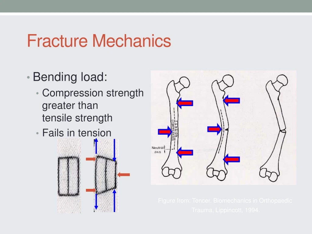
Fracture Mechanics • Bending load: • Compression strength greater than tensile strength • Fails in tension Figure from: Tencer. Biomechanics in Orthopaedic Trauma, Lippincott, 1994.
Fracture Mechanics • Torsion • The diagonal in the direction of the applied force is in tension – cracks perpendicular to this tension diagonal • Spiral fracture 45º to the long axis Figures from: Tencer. Biomechanics in Orthopaedic Trauma, Lippincott, 1994.
Fracture Mechanics • Combined bending & axial load • Oblique fracture • Butterfly fragment Figure from: Tencer. Biomechanics in Orthopaedic Trauma, Lippincott, 1994.
Biomechanics of Internal Fixation • Screw Anatomy • Inner diameter • Outer diameter • Pitch Figure from: Tencer et al, Biomechanics in OrthopaedicTrauma, Lippincott, 1994.
Biomechanics of Screw Fixation • To increase strength of the screw & resist fatigue failure: • Increase the inner root diameter • To increase pull out strength of screw in bone: • Increase outer diameter • Decrease inner diameter • Increase thread density • Increase thickness of cortex • Use cortex with more density.
Biomechanics of Screw Fixation • Cannulated Screws • Increased inner diameter required • Relatively smaller thread width results in lower pull out strength • Screw strength minimally affected (α r4outer core - r4inner core ) Figure from: Tencer et al, Biomechanics in OrthopaedicTrauma, Lippincott, 1994.
Biomechanics of Plate Fixation • Plates: • Bending stiffness proportional to the thickness (h) of the plate to the 3rd power. Height (h) Base (b) I= bh3/12
Moments of Inertia • Resistance to bending, twisting, compression or tension of an object is a function of its shape • Relationship of applied force to distribution of mass (shape) with respect to an axis. Figure from: Browner et al, Skeletal Trauma 2nd Ed, Saunders, 1998.
Fracture Mechanics 1.6 x stronger • Fracture Callus • Moment of inertia proportional to r4 • Increase in radius by callus greatly increases moment of inertia and stiffness 0.5 x weaker Figure from: Browner et al, Skeletal Trauma 2nd Ed, Saunders, 1998. Figure from: Tencer et al: Biomechanics in Orthopaedic Trauma, Lippincott, 1994.
Fracture Mechanics • Time of Healing • Callus increases with time • Stiffness increases with time • Near normal stiffness at 27 days • Does not correspond to radiographs • Figure from: Browner et al, Skeletal Trauma, • 2nd Ed, Saunders, 1998.
IM NailsMoment of Inertia • Stiffness proportional to the 4th power. • Figure from: Browner et al, Skeletal Trauma, 2nd Ed, Saunders, 1998.
IM Nail Diameter Figure from: Tencer et al, Biomechanics in Orthopaedic Trauma, Lippincott, 1994.
Slotting • Allows more flexibility • In bending • Decreases torsional strength Figure from Rockwood and Green’s, 4th Ed Figure from: Tencer et al, Biomechanics in Orthopaedic Trauma, Lippincott, 1994.
Slotting-Torsion Figure from: Tencer et al, Biomechanics in Orthopaedic Trauma, Lippincott, 1994.
Interlocking Screws • Controls torsion and axial loads • Advantages • Axial and rotational stability • Angular stability • Disadvantages • Time and radiation exposure • Stress riser in nail • Location of screws • Screws closer to the end of the nail expand the zone of fxs that can be fixed at the expense of construct stability
Biomechanics of Plate Fixation • Functions of the plate • Compression • Neutralization • Buttress • “The bone protects the plate”
Biomechanics of Plate Fixation • Unstable constructs • Severe comminution • Bone loss • Poor quality bone • Poor screw technique
Biomechanics of Plate Fixation Applied Load • Fracture Gap /Comminution • Allows bending of plate with applied loads • Fatigue failure Gap Bone Plate
Biomechanics of Plate Fixation • Fatigue Failure • Even stable constructs may fail from fatigue if the fracture does not heal due to biological reasons.
Biomechanics of Plate Fixation Applied Load • Bone-Screw-Plate Relationship • Bone via compression • Plate via bone-plate friction • Screw via resistance to bending and pull out.
Biomechanics of Plate Fixation • The screws closest to the fracture see the most forces. • The construct rigidity decreases as the distance between the innermost screws increases. Screw Axial Force
Biomechanics of Plate Fixation • Number of screws (cortices) recommended on each side of the fracture: Forearm 3 (5-6) Humerus 3-4 (6-8) Tibia 4 (7-8) Femur 4-5 (8)
Biomechanics of Plating • Tornkvist H. et al: JOT 10(3) 1996, p 204-208 • Strength of plate fixation ~ number of screws & spacing (1 3 5 > 123) • Torsional strength ~ number of screws but not spacing
Biomechanics of External Fixation • Pin Size • {Radius}4 • Most significant factor in frame stability
Biomechanics of External Fixation • Number of Pins • Two per segment • Third pin
Biomechanics of External Fixation A C Third pin (C) out of plane of two other pins (A & B) stabilizes that segment. B
Biomechanics of External Fixation • Pin Location • Avoid zone of injury or future ORIF • Pins close to fracture as possible • Pins spread far apart in each fragment • Wires • 90º
Biomechanics of External Fixation • Bone-Frame Distance • Rods • Rings • Dynamization
Biomechanics of External Fixation • SUMMARY OF EXTERNAL FIXATOR STABILITY: Increase stability by: 1] Increasing the pin diameter. 2] Increasing the number of pins. 3] Increasing the spread of the pins. 4] Multiplanar fixation. 5] Reducing the bone-frame distance. 6] Predrilling and cooling (reduces thermal necrosis). 7] Radially preload pins. 8] 90 tensioned wires. 9] Stacked frames. **but a very rigid frame is not always good.
Ideal Construct • Far/Near - Near/Far on either side of fx • Third pin in middle to increase stability • Construct stability compromised with spanning ext fix – avoid zone of injury (far/near – far/far)
Courtesy of Synthes- Robi Frigg = < Patient Load Patient Load Friction Force Patient Load Conventional Plate Fixation
Courtesy of Synthes- Robi Frigg < Compressive Strength of the Bone = Patient Load Locked Plate and Screw Fixation
Courtesy of Synthes- Robi Frigg Patient Load Preload Stress in the Bone +
Courtesy of Synthes- Robi Frigg Standard versus Locked Loading
Courtesy of Synthes- Robi Frigg Pullout of regular screws by bending load
Courtesy of Synthes- Robi Frigg Higher resistant LHS against bending load Larger resistant area
Biomechanical Advantages of Locked Plate Fixation • Purchase of screws to bone not critical (osteoporotic bone) • Preservation of periosteal blood supply • Strength of fixation rely on the fixed angle construct of screws to plate • Acts as “internal” external fixator
Preservation of Blood SupplyPlate Design LCDCP DCP
Courtesy of Synthes- Robi Frigg Preservation of Blood SupplyLess bone pre-stress • Locked Plating • Plate (not bone) is pre-stressed • Periosteum preserved • Conventional Plating • Bone is pre-stressed • Periosteum strangled
Courtesy of Synthes- Robi Frigg Angular Stability of Screws Nonlocked Locked
Courtesy of Synthes- Robi Frigg Biomechanical principlessimilar to those of external fixators Stress distribution
Courtesy of Synthes- Robi Frigg Surgical TechniqueCompression Plating • The contoured plate maintains anatomical reduction as compression between plate and bone is generated. • A well contoured plate can then be used to help reduce the fracture. Traditional Plating
Courtesy of Synthes- Robi Frigg Surgical TechniqueReduction If the same technique is attempted with a locked plate and locking screws, an anatomical reduction will not be achieved. Locked Plating
Courtesy of Synthes- Robi Frigg Surgical TechniqueReduction Instead, the fracture is first reduced and then the plate is applied. Locked Plating
Surgical TechniquePrecontoured Plates 1. Contour of plate is important to maintain anatomic reduction. Conventional Plating Locked Plating 1. Reduce fracture prior to applying locking screws.
Larger area of resistance Sequential Screw Pullout Unlocked vs Locked Screws Biomechanical Advantage 1. Force distribution 2. Prevent primary reduction loss 3. Prevent secondary reduction loss 4. “Ignores” opposite cortex integrity 5. Improved purchase on osteoporotic bone
Courtesy of Synthes- Robi Frigg Surgical TechniqueReduction with Combination Plate Lag screws can be used to help reduce fragments and construct stability improved w/ locking screws Locked Plating